Typically equivalent to receiver spacing.Single station spacing defined for each profile.see OVERLAP.PDF and RAYFRACT.PDF chapter Overlapping receiver spreads, on your CD.receiver spreads should overlap by 30% to 50%.overlapping receiver spreads, so internal far offset shots can be used for WET tomography.at least 1 shot every 3 receivers, ideally every 2 receivers.This enables correction of picking errors. more reliable with shots recorded in both directions and reciprocal shots.WET works with shots recorded only in one direction.24 or more channels/receivers per shot recommended.Survey Design Requirements and Suggestions Use two or more boreholes for improved resolution and reliability.Then import these exported uphole shots into one surface refraction profile. Walkaway VSP shots recorded with one or more boreholes may be converted to uphole shots by resorting traces by common receiver.Velocity inversions / low-velocity layers may become visible.Imaged structure/layering is blurred out. This becomes visible directly adjacent to borehole. Anisotropy: velocity may be dependent on predominant direction of ray and wave path propagation.Use 1D-gradient initial model or constant-velocity Supported Recording Geometries (cont.) Constrain surface refraction interpretation with uphole shots POISSON.PDF: determine dynamic Poisson’s Ratio from P & S wave.Combine downhole shots with crosshole shots, if all receivers in same borehole, for all shots.Surface refraction, see appended tutorials.Supported Recording Geometries Compressional (P-) wave & shear (S-) wave interpretation see RAYFRACT.HLP help file Fresnel volume or wave path approach :.WET parameters sometimes need to be adjusted, to avoid artefacts.partial modeling of diffraction, around low-velocity areas.


#REFRACTION – RAYFRACT UPDATE#
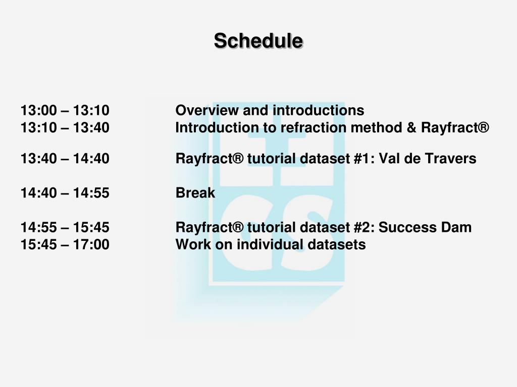
nonlinear 2D optimization with steepest descent, to determine model update for one wavepath.rays that arrive within half period of fastest ray : tSP + tPR – tSR Delta-t-V artefacts are completely removedĢD WET Wavepath Eikonal Traveltime inversion.generated from top by lateral averaging of velocities.based on synthetic times for Broad Epikarst model (Sheehan, 2005a, Fig.1D Delta-t-V velocity-depth profile below each station.Smooth Inversion = 1D gradient initial model +2D WET Wavepath Eikonal Traveltime tomography Get minimum-structure 1D gradient initial model : Top : pseudo-2D Delta-t-V display Schedule 13:00 – 13:10 Overview and introductions 13:10 – 13:40 Introduction to refraction method & Rayfract® 13:40 – 14:40 Rayfract® tutorial dataset #1: Val de Travers 14:40 – 14:55 Break 14:55 – 15:45 Rayfract® tutorial dataset #2: Success Dam 15:45 – 17:00 Work on individual datasets EEGS Short CourseProcessing of Seismic Refraction Tomography Data SAGEEP 2010 Keystone, Colorado April 10, 2010


 0 kommentar(er)
